



Engineering · Assessment & retrofit of existing structures
When an existing building has to carry more load, resist earthquakes to today’s standards, or win back capacity lost to corrosion and damage, demolition is rarely the right answer. SARP assesses the structure, calculates exactly what is missing, and closes the gap with Mapei’s certified composite and high-performance mortar systems: thin, light and fast to install.
Everything sits under one roof. Our ISO/IEC 17025-accredited laboratory tests the materials, our engineers carry out the calculations to Eurocode and the international design guides for composites, and as Mapei’s distributor in Albania we supply the certified systems and stay on site until acceptance tests prove that the strengthening performs as designed.
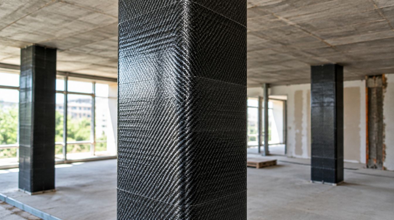
When a structure needs strengthening
- Change of use or new loads. Offices turned into archives, roofs fitted with plant or photovoltaics, extra storeys, heavier finishes.
- Seismic upgrade. Buildings designed before modern capacity-design rules, with weak columns, short lap splices, too few stirrups or soft storeys. The November 2019 Durrës earthquake showed how much of Albania’s building stock falls into this group.
- Openings and alterations. New openings in slabs or load-bearing walls, columns or walls removed during renovation.
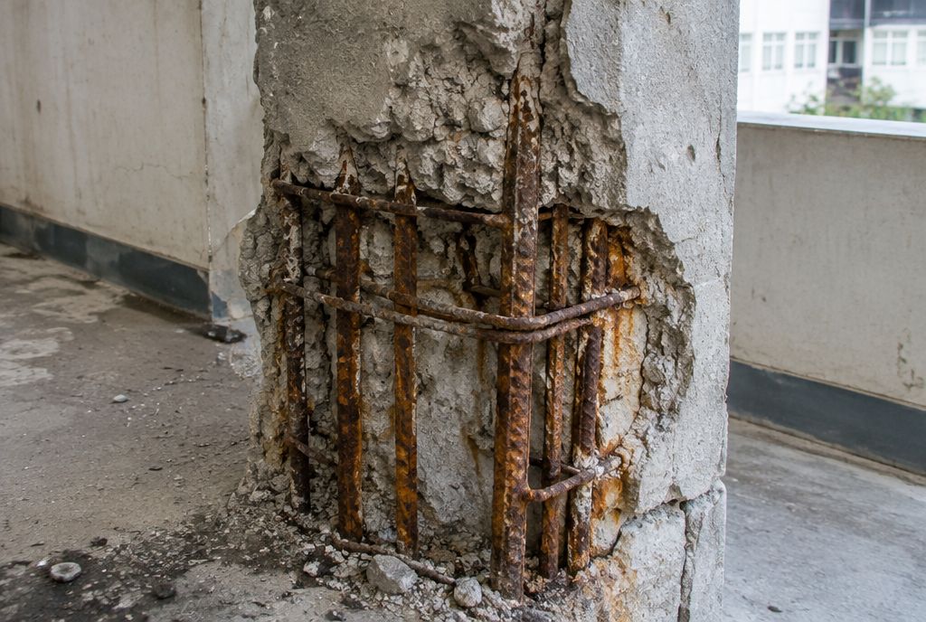
- Deterioration. Reinforcement corroded by carbonation or by chlorides in coastal areas, spalled cover and section loss.
- Design or construction defects. Concrete below the specified class, missing or misplaced bars, excessive deflection or cracking.
- Damage. Cracking after an earthquake, fire, impact or settlement, where the remaining capacity must be proven and then restored.
Our method, from survey to handover
-
Documentation & visual survey
We collect the original drawings, calculations and history of the building, then map cracks, deflections, corrosion and moisture. The damage pattern often reveals the mechanism before any calculation is run.
-
Geometric & reinforcement survey
We measure members and spans, and scan for reinforcement to establish bar size, spacing and cover. We open the concrete in a few places to confirm what the scans show.
-
Testing campaign
Cores, non-destructive tests, rebar samples and durability tests, planned to reach the knowledge level the project needs (see testing).
-
Modelling & assessment
A structural model of the existing building, analysed to EN 1998-3 (linear or pushover), shows which members fail, by which mechanism and by how much. This is the basis for every strengthening decision.
-
Option study & design
We compare candidate systems on capacity, added mass and stiffness, thickness, fire, durability, downtime and cost. The chosen solution is dimensioned and fully verified in a calculation report with drawings and a method statement.
-
Execution & acceptance
Certified Mapei materials, substrate preparation to the system manual, environmental logging during installation, and on-site pull-off and witness-sample testing, all documented in an as-built report.
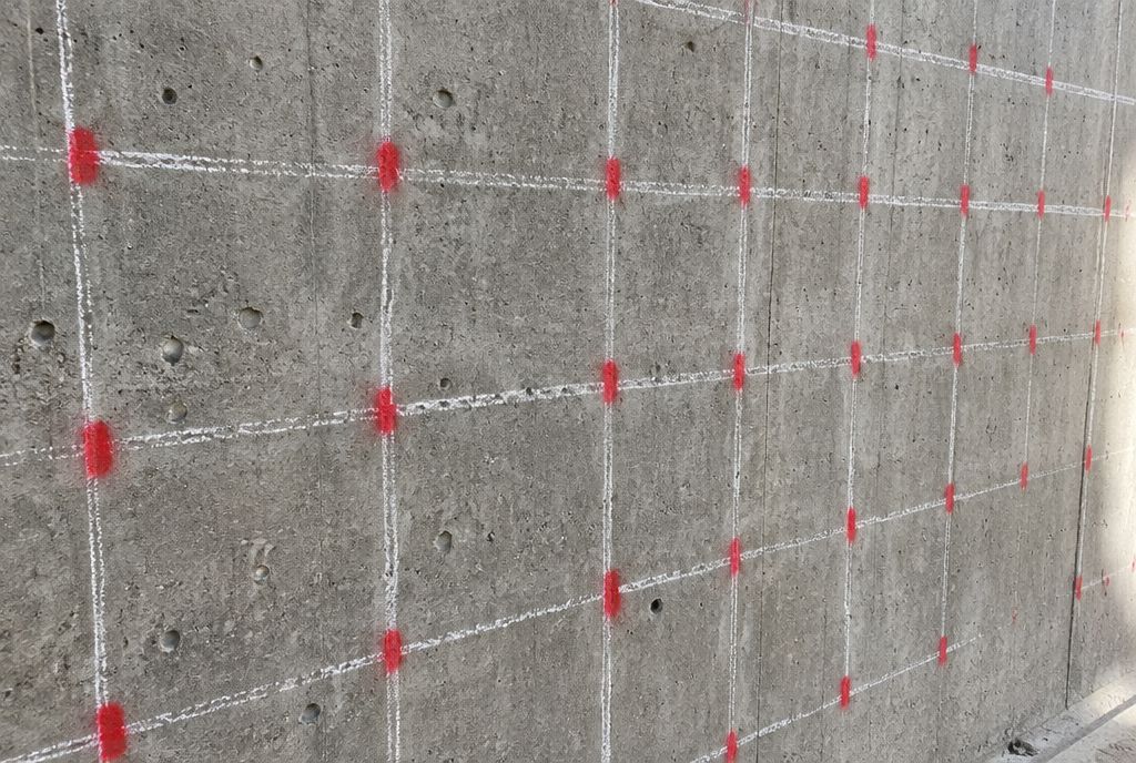
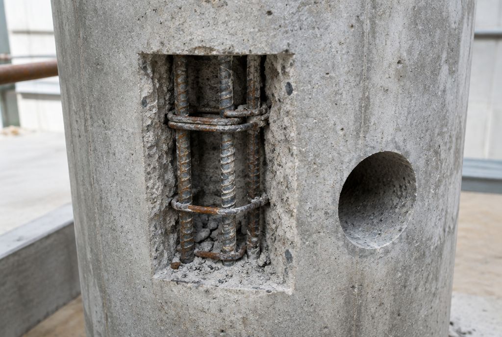
Field and laboratory investigation
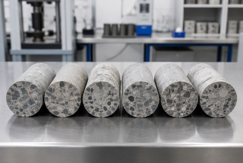
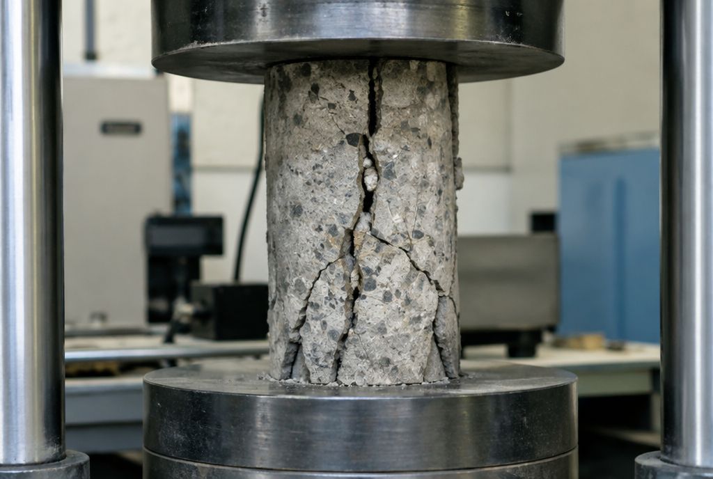
An assessment is only as reliable as the material data behind it. Eurocode 8-3 links the depth of investigation to a knowledge level (KL1 limited, KL2 normal, KL3 full), which sets the confidence factor applied to material strengths: CF = 1.35, 1.20 or 1.00. Moving from KL1 to KL3 can raise usable material strengths by about a third. Investing in testing is often the single biggest saving in a strengthening project.
| Test | What it tells us | Reference |
|---|---|---|
| Concrete cores, compressive strength | In-situ concrete strength used in the assessment, and calibration of the non-destructive tests | EN 12504-1 · EN 13791 |
| Rebound hammer | Surface hardness and uniformity. Maps weak zones and guides where to core | EN 12504-2 |
| Ultrasonic pulse velocity | Homogeneity, voids, honeycombing and crack depth. Combined with rebound (SonReb) for wider strength estimates | EN 12504-4 |
| Cover meter / GPR scanning | Bar position, diameter, cover and stirrup spacing, plus clear zones for drilling and anchors | BS 1881-204 |
| Reinforcement sampling | Yield and tensile strength and elongation of the existing steel, which control ductility checks | EN ISO 15630-1 · ISO 6892-1 |
| Carbonation depth | Whether the carbonation front has reached the bars, which decides whether to repair before strengthening | EN 14630 |
| Chloride content | Chloride-induced corrosion risk, critical for coastal structures | EN 14629 |
| Half-cell potential | Probability of active corrosion across a surface | ASTM C876 |
| Substrate pull-off | Surface tensile strength. Confirms the substrate can anchor a bonded FRP or FRCM system | EN 1542 |
| Masonry flat-jack tests | In-situ stress, compressive strength and deformability of masonry walls | ASTM C1196 · C1197 |
| Masonry units & mortar | Compressive strength of bricks or blocks and of joint mortar | EN 772-1 · EN 1015-11 |
| Load test (where required) | Direct proof of behaviour under service load, before or after strengthening | Project protocol |
Laboratory work is carried out by SARP & LAB. See the concrete, reinforcement, non-destructive and masonry testing pages for the accredited scope.
The calculations we deliver
Every intervention is backed by a calculation report that a checking engineer or the authorities can follow line by line. It covers material values with their confidence factors, load combinations, the capacity and demand of each member before and after strengthening, and detailing for anchorage and execution.
Global behaviour
- Structural model of the existing building, calibrated on survey and test data
- Linear and nonlinear static (pushover) analysis to EN 1998-3, checked at the Damage Limitation, Significant Damage and Near Collapse limit states
- Capacity/demand ratios for every member and mechanism, before and after the intervention
- Check that strengthening does not shift the problem: added stiffness and mass, new weak storeys, foundation demand
Masonry structures
- In-plane shear (diagonal cracking and sliding) and in-plane bending of walls and spandrels
- Out-of-plane local mechanisms (overturning and bending of walls) by kinematic analysis
- Arches and vaults: thrust line and hinge mechanisms, extrados and intrados reinforcement
- Wall-to-floor and wall-to-wall connections
Reinforced-concrete members
- Bending: ultimate moment with FRP plates or fabrics, including end and intermediate-crack debonding checks and anchorage lengths
- Shear: FRP contribution from U-wraps or full wraps, using the effective design strain, plus mechanical anchorage where needed
- Column confinement: confined strength and ultimate strain, axial capacity, chord-rotation and ductility gain for seismic checks
- Beam-column joints: joint shear with multi-axial fabrics
- Slabs: thin high-performance overlays acting compositely with the existing slab, and shear transfer at the interface
- Serviceability: stresses, deflections and crack widths after strengthening
- Fire and durability: capacity of the unstrengthened member under the accidental fire combination, environmental reduction factors for composites, and fire protection where required
Design references
- EN 1998-3 Eurocode 8: assessment and retrofitting of buildings
- EN 1992-1-1 · EN 1996-1-1 design of concrete and masonry structures
- CNR-DT 200 R1/2013 design of FRP strengthening systems
- CNR-DT 215/2018 design of FRCM strengthening systems
- ACI 440.2R guide for externally bonded FRP systems
- fib Bulletin 90 externally applied FRP reinforcement for concrete
- EN 1504 series: repair and protection of concrete structures
- Mapei Structural Design calculation software developed by Mapei with Eucentre, cross-checked against our own models
The Mapei systems we design with
Mapei’s strengthening range covers reinforced concrete, masonry, steel and timber. The FRP, FRCM, CRM and HPC systems carry CVT technical evaluation certificates under the Italian qualification guidelines (with CE marking where applicable). We specify every product from Mapei’s own design data and installation manuals.
FRP · fibre-reinforced polymers
MapeWrap fabrics
- MapeWrap C UNI-AX: unidirectional carbon fabric for bending, shear and confinement
- MapeWrap C UNI-AX HM: ultra-high-modulus carbon, where stiffness governs
- MapeWrap C BI-AX / QUADRI-AX: multi-directional carbon for joints and complex stress fields
- MapeWrap G UNI-AX: glass fabric, well suited to masonry, arches and vaults
FRP · pultruded plates
Carboplate & Carboplate W
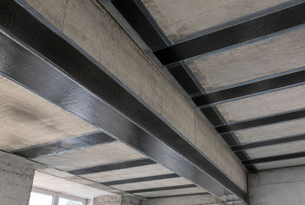
Preformed carbon-fibre plates bonded to the tension face of beams and slab soffits for maximum flexural gain at minimum thickness. They are installed with the MapeWrap epoxy family: MapeWrap Primer 1, MapeWrap 11/12 (levelling and bonding), MapeWrap 21 (wet lay-up) and MapeWrap 31 (dry lay-up).
FRCM · fabric-reinforced mortar
FRCM System Mapegrid G
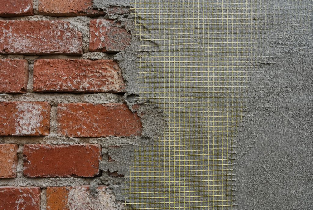
Alkali-resistant glass mesh Mapegrid G 220 embedded in Planitop HDM Maxi, a high-ductility fibre-reinforced pozzolanic mortar. It is breathable, compatible with masonry and performs better in fire than resin-based systems. It suits walls, arches and vaults.
CRM · composite-reinforced mortar
CRM System Mapenet EMR 33 / 66 / 99
Pre-formed composite meshes in a structural mortar coat for the in-plane and out-of-plane strengthening of masonry and the jacketing of concrete elements. The three mesh sizes let us match strength to demand.
Mortar-based, no mesh
Planitop Intonaco Armato
Micro-reinforced, cement-free mortar that raises the shear and tensile strength of masonry walls without mesh and without a significant increase in mass or stiffness. Ideal where a fast, thin seismic render is the optimum.
High-performance concrete
Planitop HPC line
- Planitop HPC: fibre-reinforced high-performance mortar for thin jacketing of columns and beams
- Planitop HPC Floor / Floor 46 / Floor 46 T: thin, steel-fibre-reinforced toppings that raise slab capacity and stiffness from above
Anti-overturn · anti-collapse
MapeWrap EQ System & Mapegrid G 120
Seismic “wallpaper” that stops infill walls overturning and prevents slab soffits from falling, without dowels and with fast return to service. Mapegrid G 120 with Planitop HDM Maxi handles local strengthening.
Connections
Anchors, cords & helical bars
- MapeWrap C / G / B / SG Fiocco: fibre cords for structural connections and FRP anchorage
- MapeWrap C Connector: pultruded carbon connectors for anchoring ties
- Mapei Steel Dry: AISI 316 helical bars for crack stitching and wall-to-floor ties
Before strengthening
Concrete repair to EN 1504
Where corrosion is active the substrate is restored first. We break out unsound concrete, clean and passivate the bars, and rebuild the section with Mapei structural repair mortars, so that the strengthening bonds to sound, durable concrete.
Choosing the optimum solution for the problem
No single system is best everywhere. We start from the failure mechanism the assessment reveals and choose the lightest, thinnest and most durable intervention that closes the gap with an adequate margin. That also keeps the building in use for as much of the work as possible.
| Problem found | Typical optimum | Why | Alternative when… |
|---|---|---|---|
| Beam or slab short of bending capacity | Carboplate on beams; MapeWrap C UNI-AX on slab soffits | Highest strength gain for 1–3 mm and negligible weight, with no loss of headroom | Access is from above or deflection governs: Planitop HPC Floor topping |
| Shear deficiency in beams | MapeWrap C UNI-AX U-wraps or full wraps, anchored with MapeWrap C Fiocco / Connector | Adds shear capacity without enlarging the section | Very high demand: Planitop HPC jacketing |
| Columns lacking ductility or axial capacity | MapeWrap C UNI-AX confinement wrapping | Large gain in ductility and chord-rotation capacity, with no added stiffness to attract seismic force | Bending capacity also needed: Planitop HPC thin jacket |
| Weak beam-column joints | MapeWrap C QUADRI-AX / BI-AX | Multi-directional fibres follow the joint stress field | Combined with column wrapping for a complete node |
| Masonry walls weak in shear | CRM Mapenet EMR or FRCM Mapegrid G 220 + Planitop HDM Maxi | Breathable, compatible with masonry, good fire behaviour | Thin render with no mesh wanted: Planitop Intonaco Armato |
| Infill walls at risk of overturning; slab soffits spalling | MapeWrap EQ System | Fast, dowel-free, quick return to service | Local zones: Mapegrid G 120 + Planitop HDM Maxi |
| Arches and vaults | FRCM Mapegrid G 220 + Planitop HDM Maxi at the extrados | Prevents hinge formation and keeps the masonry breathable | Intrados only accessible: MapeWrap G UNI-AX |
| Poor wall-to-floor ties, cracked masonry | Mapei Steel Dry helical bars; MapeWrap Fiocco connections | Restores box behaviour, the first defence in an earthquake | Combined with wall strengthening |
| Corroded reinforcement | EN 1504 repair first, then strengthening | Bonding to unsound concrete wastes the system | Section loss beyond repair: member replacement |
How we optimise: each option is scored on the capacity it adds, the mass and stiffness it adds (decisive under seismic loads), thickness and architectural impact, fire exposure, moisture and breathability, durability, installation time and disruption, and whole-life cost. We present the comparison so you can see why the recommended solution is the right one.
Quality control on site
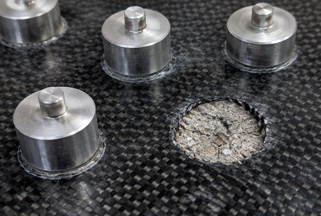
- Substrate acceptance: pull-off tests (EN 1542) to confirm the minimum surface tensile strength required by the system, typically about 1.5 MPa for bonded FRP on concrete
- Surface preparation: grinding or blasting, rounding corners to the required radius, and levelling with MapeWrap 11/12 before application
- Environmental logging: air and substrate temperature, humidity and dew point recorded during every resin application
- Traceability: batch numbers and CVT certificates for every system installed
- Witness samples: laminates made on site in parallel with the works and tensile-tested to confirm the design properties
- Bond verification: pull-off tests on the installed FRP and tap testing to detect delamination
- Protection: UV, fire or finish coatings applied as specified
- As-built report: drawings, test results, logs and certificates, ready for the client and the authorities
Why SARP
Lab, design and supply in one team
The engineers who design the strengthening use test data from our own accredited laboratory, so assumptions are replaced by measured values.
Mapei’s distributor in Albania
Direct access to the full Mapei range, its technical service and certification documents, with materials available locally.
Related services
Combine strengthening with a full seismic assessment or a structural inspection of the building.
Send us drawings, photos or a short description of the problem. We’ll propose an investigation plan and a first estimate of the options.